Introduction
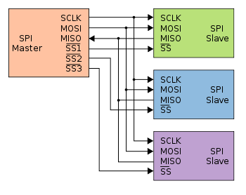
The serial peripheral interface (SPI) provides serial communication between devices such as microcontrollers, DSPs, DACs, and ADCs. Typically, these serial interfaces are single-ended and are in close proximity. Differential line circuits increase the allowable distance between devices, while maintaining data integrity.
Motorola introduced the serial peripheral interface (SPI) as a means of communication with a microprocessor.
McBSP and SPI are traditionally single–ended and the master and slave are within close proximity of each other and do not extend off board (< 30 cm). The challenge is to increase the distance (extend off board), maintain data rate, and successfully deal with the radiated emissions (electromagnetic interference or EMI), susceptibility to noise, and transmission line reflections.
Transmission line reflections occur when the termination impedance does not match the characteristic impedance of the transmission line. This matching is increasingly important as the signal transition time decreases relative to the propagation time through the transmission media. When the minimum signal transition time (the smaller of either the rise or fall time) is less than three times the one-way propagation time of the transmission media, then impedance matching is recommended.
In addition to transmission line reflections, the signal transition time and interconnect length impact radiated emissions and susceptibility. The higher frequencies represented in faster signal transitions more easily radiate through inductive and capacitive coupling, and longer lines allow more coupling from adjacent circuits. In single-ended interfaces, emissions coupled as noise add or subtract directly from the signal transmitted.
Increasing both signaling rate and distance with a single-ended interconnect results in more radiated emissions and noise susceptibility. One way to alleviate these issues and provide higher signaling rates over distance is the use of differential signaling. Differential interfaces generate electric fields just as single-ended interfaces; however, with differential signaling there are two equal and opposite fields[1]. If tightly coupled, these fields cancel in the far field (relative to the wavelength of the radiated emission), since the resulting
electric fields are equal in magnitude and opposite in phase.
The tight coupling of differential pairs also helps minimize noise susceptibility. Emissions coupled as noise add or subtract directly from the signal transmitted on each line, just as in single-ended circuits. The difference with the differential circuits is that the external noise is equally induced on each conductor, and the receiver rejects the induced noise.
Differential signaling can be accomplished with TIA/EIA-422 (RS-422), TIA/EIA-485 (RS-485), TIA/EIA-644 (LVDS), or TIA/EIA-899 (M-LVDS) standard compliant interface circuits. Choosing a differential interface standard is application dependent, since there are different benefits with each. Generally, the RS-485 or RS-422 standard parts have a maximum signaling rate of 30Mbps, a larger voltage swing than the LVDS and M-LVDS parts, and provide a larger common-mode voltage range. LVDS or M-LVDS produce less EMI, consume less power, and operate at faster signaling rates. LVDS or M-LVDS are found more often in applications where speed is a critical factor, while RS-485 or RS-422 are found in applications where noise and distance are greater.
Suggested solution
Following is a suggested solution for transfering SPI data over large distances (10-20m) over standard UTP cable.
For the transmission part I used the MAX3032E interface chip from Maxim semiconductor. The MAX3030E - MAX3033E family of quad RS-422 transmitters send digital data transmission signals over twisted-pair balanced lines in accordance with TIA/EIA-422-B and ITU-T V.11 standards. All transmitter outputs are protected to ±15kV using the Human Body Model. The MAX3030E-MAX3033E are available with either a 2Mbps or 20Mbps guaranteed baud rate. The 2Mbps baud rate transmitters feature slew-rate-limiting to minimize EMI and reduce reflections caused by improperly terminated cables.
The 20Mbps baud rate transmitters feature low-static current consumption (ICC < 100µA), making them ideal for battery-powered and power-conscious applications.
On the following image is shown the transmitting part of the circuit:
In this case I only used MOSI and SCK signals, since I was using the SPI to drive a RGB light strip. I separated the output in two, so I can drive two independent strips. If you want to know more about these light strips you can check out the excellent tutorial here: http://learn.adafruit.com/digital-led-strip
The receiving side is given in the next picture:

Receiving chips are MAX3280E, which are single receivers designed for RS-485 and RS-422 communication. These devices guarantee data rates up to 52Mbps, even with a 3V power supply. Don't forget to terminate the transmission lines properly using 100 ohm resistors.
Conclusion
Increasing both distance and signaling rate in traditionally single-ended applications such as the SPI and McBSP introduces design issues. These issues include noise susceptibility, EMI, and transmission line reflections. These issues are mitigated with matched terminations and differential signaling such as, LVDS, M-LVDS, RS-485, or RS-422. I tried to offer a solution which I personally tested and proven to work reliably over distances up to 20m, using a normal UTP cable.
No comments:
Post a Comment